![]() Adding hosts to map from monitoring database
Adding hosts to map from monitoring database
![]() Adding indicators and charts to map
Adding indicators and charts to map
![]() Changing color, pattern, shading
Changing color, pattern, shading
![]() Aligning objects around switches
Aligning objects around switches
![]() Editing object properties, group editing
Editing object properties, group editing
![]() Adding links to other maps or documents
Adding links to other maps or documents
![]() Displaying monitored parameter values on object captions
Displaying monitored parameter values on object captions
![]() Copying to clipboard and pasting objects
Copying to clipboard and pasting objects
![]() Undoing and redoing last actions
Undoing and redoing last actions
To add an object to your map:
1. Open the necessary object category on the objects pane.
2. Select the required object.
3. Drag the object to the workspace.
The object on the diagram will appear at the position where it has been dropped.
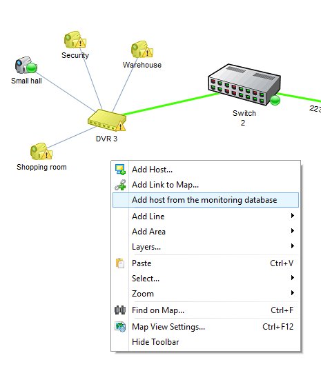
![]() Adding hosts to map from monitoring database
Adding hosts to map from monitoring database
If you already have hosts being monitored, it will be quite easy to add them to your graphic network map. You need to import these hosts from the database to the map, and align the icons using the aligning functions. If you want to import all the existing hosts to your map, click the Import button and select Import hosts from monitoring database in the dropdown list. All hosts will be aligned as a table in this case.
If you have a network diagram file created by our network diagramming tools 10-Strike Network Diagram or 10-Strike LANState, you can import it as is. Select From map file... in that dropdown menu to do this.
If you want to add only selected hosts to the map, display the map's context menu and click Add host from the monitoring database. Select necessary hosts on the host list displayed, and click OK.
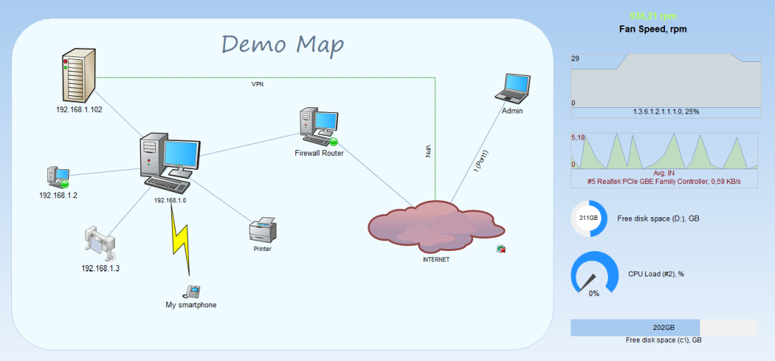
![]() Adding indicators and charts to map (create a SCADA-like diagram)
Adding indicators and charts to map (create a SCADA-like diagram)
Widgets and indicators described in previous topics can be placed directly to the map near with host icons but not only on a separate dashboard window. This can be helpful for displaying critical parameter values on a common map which can be observed on a large screen. Learn more about this....
All the commands for changing parameters of object texts are available on the toolbar.
Editing text
To edit the text caption of an object:
1. Select the object on the map.
2. Double-click on the object to activate the text editing mode.
3. Make the necessary changes in the mini-editor that appears.
4. Click on the same object or on a blank spot of the workspace.
When editing text, you can insert line feeds by pressing the Enter key. The entry field will be resized automatically.
Changing text font
To change a text font:
1. Select the object on a diagram.
2. Select the desired font on the
list on the toolbar.
When selecting a font for labeling diagonal lines, please keep in mind that not all the fonts can be displayed at an angle.
Changing font size
To change a font size:
1. Select the object on a diagram.
2. Select the desired font size on the
list on the toolbar.
You can also enter a custom font size in this field.
Changing text color
To change a text color:
1. Select the object on a diagram.
2. Select the desired text color on the
list on the toolbar.
You can also set any other color that is not available on the list; simply select Custom... on the list.
In the color selection dialog, select the desired color and then click OK.
Changing text style
To change a font style:
1. Select the object on a diagram.
2. On the toolbar, click on the
buttons to set the desired style: B - bold, I - italic, U - underlined. You can use any combinations of the styles.
Aligning text
The text part of an object can be aligned both vertically and horizontally. To align a text:
1. Select the object on a diagram.
2. On the toolbar, click one of these buttons
to align the text horizontally or one of these
to align it vertically.
Changing line width
This command is applicable only to objects of the Line type. To set a line width:
1. Select the line object on a diagram.
2. Click on the arrow area of the
button on the toolbar.
3. Select the desired width on the menu that appears.
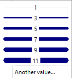
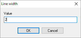
You can set any other line width by selecting Other... on the menu and then entering the desired width in the Value field.
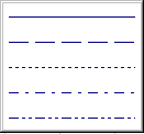
Changing line pattern
This command is applicable only to objects of the Line type. To set a line pattern:
1. Select the line object on a diagram.
2. Click on the arrow area of the
button on the toolbar.
3. Select the desired line pattern on the menu that appears.
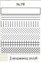
Changing fill pattern
This command is applicable only to objects of the Area type. To set a fill pattern:
1. Select the area object on a diagram.
2. Click on the arrow area of the
button on the toolbar.
3. Select the desired fill pattern on the menu that appears.
You can make the area completely transparent by selecting the No fill value.
To fill an area with a color while keeping it transparent, select the Transparency On/Off on the menu. However, please keep in mind that not any color allows an area to be transparent.
Changing fill color
To change a fill color (line color):
1. Select the object on a diagram.
2. Select the desired color on the
list on the toolbar.
You can also set any other color that is not available on the list; simply select Custom... on the list.
You can view or edit the object's properties on the Object Properties window. To bring up the window, select an object and select Properties... in the context menu.
The application allows connecting with lines only objects of the Device type. There are three ways to connect two diagram objects with a line:
Method 1:
1. Enable the line drawing mode by selecting the main or context menu item "Line Drawing Mode". The program will lock the device layer so you will not be able to move or resize anything.
2. Place the mouse cursor on a device. Click the left mouse button and move the cursor to another device to be connected together.
3. Release the left mouse button to create a line.
4. To disable the line drawing mode, select the main or context menu item "Line Drawing Mode" again.
Method 2:
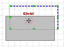
1. Place a line object on a diagram.
2. Select the line, move the mouse pointer to one of the corners of the line region. The pointer should now change to
.
3. Grab the corner (hold the left mouse button pressed); the square dot underneath the pointer should change its color to red.
4. Move the mouse pointer to the device object and then release the left mouse button.
5. Move the mouse pointer to the other object and do the same with the opposite corner of the line region.
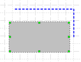
Method 3:
1. Place a line object on a diagram.
2. Drag the objects to the ends of the line.
3. Click on the line region. The devices are now connected.
To disconnect two objects, simply drag the line away from the devices.
To draw a polyline:
1. Draw a regular straight line.
2. Click on it via the left mouse button, then bring up the line menu, and click the "Line - Add node" item.
Now you can move the node in any direction and the polyline will behave like an entire entiry.
To delete (or move) a segment from the polyline, remove selection from the line, hold SHIFT, and move the segment.
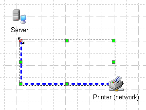
To move an object over the workspace:
1. Select one or several objects (use the Shift key to select multiple objects or select the area with the objects using the mouse pointer).
2. Place the pointer over one of the selected objects and then click on it.
3. Hold the left mouse button pressed and move the mouse in the direction required. The objects will be moved along with the pointer.
4. Release the left mouse button.
To cancel the object selection, simply click on a blank spot of the workspace.
For more precise object placement on the diagram, you can use the object alignment function. You can align objects horizontally (by left or right side, by center, on equal distance), vertically (by top or bottom, etc.), in table (in rows and columns), and in circle. The circle alignment is useful when you want to align object around their common center (for example, computers around hub, switch, or server). If a circle radius is not large but there are a lot of devices, they can be placed in two circles to avoid icon overlapping.
To arrange a set of objects on the workspace:
1. Select one or several objects (hold the Shift key to select multiple objects or select the area with the objects using the mouse pointer).
2. Place the mouse pointer over one of the selected objects and make a right-click on it to display the context menu. Select the Align... menu item.
3. Select an arrangement method on the dialog window.
4. Click OK.
![]() Aligning objects around switches
Aligning objects around switches
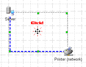
To quickly drag an icon connected to a switch to some place on the map, hold SHIFT and click on that place on the connection line where you want the icon to be moved.
You can use this feature when you do not want to scroll the map searching to that device icon following the line, and then drag it back over the whole map.
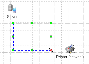
The application allows resizing objects of all types freely. To resize an object:
1. Select the object to be resized.
2. Move the mouse pointer to one of the green square dots of the object selection area. The pointer will change its look to one of these:

.
3. While holding the left mouse button pressed, move the mouse in the direction required. The objects will resize automatically.
4. Release the left mouse button.
![]() Editing object properties, group editing
Editing object properties, group editing
You can edit object properties using not only the toolbar controls. You can also use the object properties dialog window for the single or group object editing. To edit multiple objects at once:
1. Select necessary objects on the map, bring up the context menu using the right mouse button, and select Properties.
2. Edit necessary parameters and click OK.
The changes will be applied to all the selected objects. We recommend you using group editing for objects of only one type (lines, areas, hosts) at once.
![]() Adding links to other maps or documents
Adding links to other maps or documents
Any map object can represent a link to other map or any document. To open the link on the network map, hold the CTRL button on the keyboard and click on the object. The link URL can be configured in the object properties (see the previous topic above). You can create a navigation system for several maps using these links. The links are fully functional in the Pro version's web interface too.
If you want to open linked documents in the web interface, please place the documents to the ...\10-Strike Network Monitor Pro\web\docs\ folder. If there is no docs sub-folder in the web folder, it is necessary to create it. The local file path can be any in the link's URL. The main condition is the document file name should be the same in the web\docs folder as in the local folder.
The "Link to Map" object allows you to not only go to another map when you click the link, but also to get the information about the status of hosts on the linked map. The link icon turns red if there are failed hosts on that map. You can disable this feature by enabling the Do not get map status option.

![]() Displaying monitored parameter values on object captions
Displaying monitored parameter values on object captions
The program can display monitored parameter values (received during the check execution from network devices) on the area, line, and device icon captions. You can create several text areas near a device icon and display values of the monitored parameters on it (for example, this can be the CPU usage, free RAM size, or free disk space). You can also display current network bandwidth on map lines representing real network connections.
The parameter values can be included into the caption text using special tags which should be added to the object's caption.
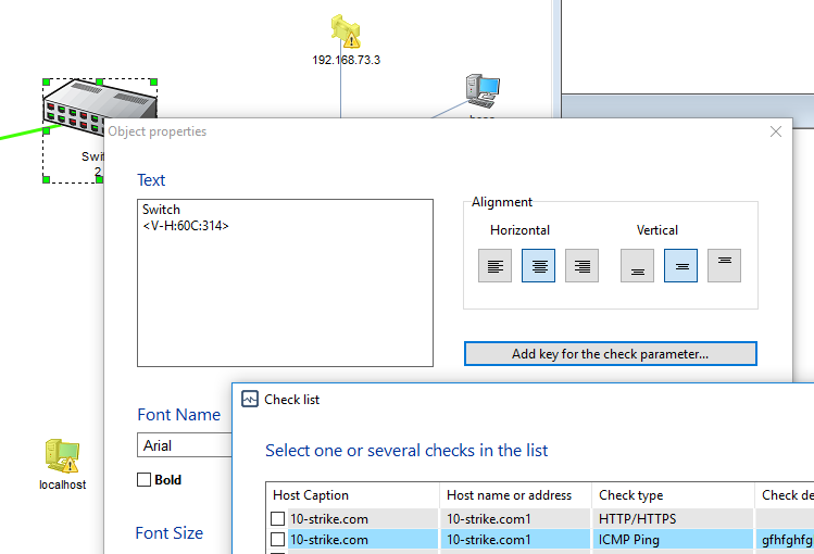
The tags (substitutions keys) are generated automatically. To add a tag to the caption text, you just need to choose a check for getting the data from it. Open the Object properties dialog (use the object's context menu - Edit | Format...) and click the Add key for the check parameter... button. The list with all checks will be displayed. Select one check. The tag will be generated. It contains two parts. The first part is the V- prefix. The second part is the host and check identifier. The tag should be included into the <> symbols. You can now insert the generated tag to any part of the object's caption (the Text field).
![]() Copying to clipboard and pasting objects
Copying to clipboard and pasting objects
To copy objects to clipboard for further pasting them to the same or other Network Diagram document:
1. Select the objects to be copied.
2. Open the context menu for the selected objects and then select Copy (or press Ctrl + C).
3. Open the context menu over a blank spot of the workspace in this or another document, open and then select Paste (or press Ctrl + V). The object or the group of objects will be replicated.
To have the source object deleted upon pasting (moving the object), select Cut (or press Ctrl + X ) instead selecting Copy.
To copy an object or a group of objects to the clipboard for further pasting them to a Microsoft Office or other document, copy them as Windows Metafile. For that purpose:
1. Select the objects to be copied.
2. Open the context menu for the selected objects and then select the Copy as Windows Metafile item on the menu.
3. Switch to the other application window and paste the content from the clipboard to it.
![]() Undoing and redoing last actions
Undoing and redoing last actions
The application keeps track of the infinite number of last actions performed over objects. To undo the last action, select the Edit | Undo item on the main menu. To redo the undone action, select the Edit | Redo item on the main menu.
Objects on a diagram can overlap one another. By default, when a Device object is added on a diagram, it is placed on top of all other objects. However, you may need to change the order of placement for the overlapping objects. For that purpose:
1. On the diagram, select the object to be removed from the topmost layer.
2. Open the context menu and then select the Send to Back item. The object that was behind the object you have just moved will automatically be placed at the very front.
Similarly, you can move an object the other way, from the back to the front, by selecting its edge not overlapped by other objects and then clicking on the Send to Front menu item. These actions can be performed over several objects simultaneously, selecting each one of them while holding the Shift key down.
You can quickly swap two overlapping objects bypassing the context menu. For that purpose:
1. Click once to select the object that is currently in the front.
2. Clicking on the same object the second time on the area where it overlaps other object, will send it to back.
To search for an object (device, line, area) on the network diagram:
1. Select the Edit | Find on map... menu item.
2. On the Find text dialog window, select a search area and type the text to search in object names, descriptions, and host addresses.
3. Click OK.

The found objects will be enclosed with a frame and the program will scroll the diagram so the objects will become visible. Use the Case sensitive and Whole words only options for more exact searching.
To delete an object or a group of objects:
1. Select the object or a group of objects to be deleted.
2. Open the context menu for the selected objects and then select the Delete item or simply press the Del key on the keyboard.
You can lock the line and area layers for more comfortable map editing (moving objects, editing properties). This helps to avoid moving lines and areas when you are working with map objects. A group of objects can be selected and moved much easier when the layers are locked.
To lock the line or area layer, select the main menu item Lock line layer or Lock area layer. After doing this, lines and/or areas will not be selected when you click them by a mouse button. You will not be able to move or delete them while the layers are locked.
In order to unlock the layers, select the same main menu items.
The program stores current map's visual settings in its map file. To open the Visual Map Settings window (Fig. 1), select the main menu's item "View | Visual map settings".
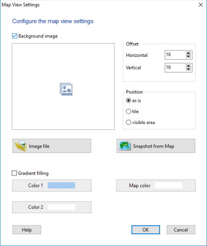
Here you can change the current map's appearance settings:
- Set a background color
- Enable the gradient filling (you should specify the window's top and bottom colors; the background color will be set automatically by finding the average color)
- Add a background image: You can draw the building plan in any graphics editor, save the image to a file, and use it as a wallpaper for your map. When using this option, the gradient background option will be unavailable
To add a background image to your map for better looking:
- Enable the Background image option and click the Image file... button.
- Select the Position option. For room plans, we recommend the as is option. For logos - tile or visible area.
- In the Offset section, configure margins for the top and left map borders. The default value is 16 pixels to avoid the image being drawn over the scroll bars.
Click OK to save the changes.
You can use images saved from Google Maps as background images. To import a map image, click the Google Maps... button. On the dialog displayed, select a map type (map, satellite, etc.), configure the map size (the final image's size) and the scale factor.
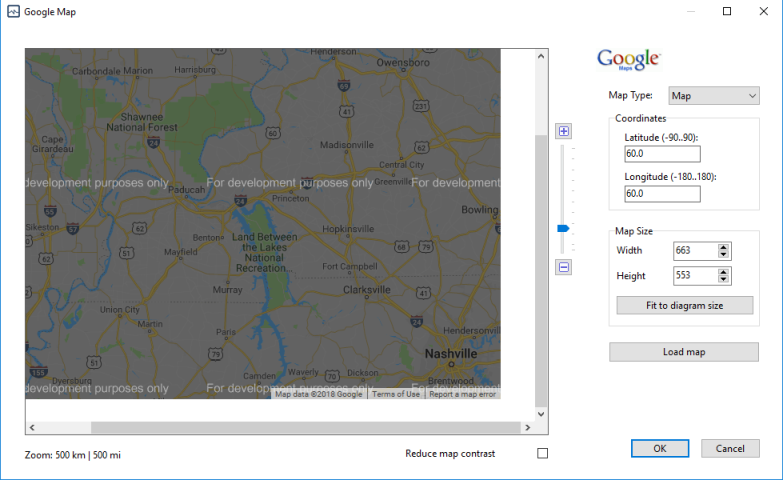
The scale parameter can be configured using the control to the right of the map with help of a mouse pointer. Or you can make double clicks on the map. The left mouse button zooms the map in, the right button zooms out.
The coordinates options help you to quickly display a necessary location on the map. The map size can be adjusted automatically to your network diagram size by clicking the Fit to diagram size button.
After changing the Map size and Coordinates parameters, you need to click the Load map button to refresh the map view.
After adjusting all the options, press the Save map as background button. The program will create an image file with the map view and link this file to your current network diagram.