Drawing Lines and Areas on Network Maps
Drawing Lines
![]() For better understanding of your network model,
you can "connect" devices on your network map with symbolic lines imitating cable connections. You can use different styles of lines (hachures, dots, etc.) and colors.
For better understanding of your network model,
you can "connect" devices on your network map with symbolic lines imitating cable connections. You can use different styles of lines (hachures, dots, etc.) and colors.
![]() To draw the connections: switch to the line adding mode by selecting the menu item Edit | Lines | Add & edit mode or by using the context menu. The cursor will became cruciate. Then select the first device to be connected, press the
left mouse button and move the mouse pointer to the other device while holding the mouse button down (or to any other place of map). Now release the button.
You will see the red line, which connects the two devices or places.
To draw the connections: switch to the line adding mode by selecting the menu item Edit | Lines | Add & edit mode or by using the context menu. The cursor will became cruciate. Then select the first device to be connected, press the
left mouse button and move the mouse pointer to the other device while holding the mouse button down (or to any other place of map). Now release the button.
You will see the red line, which connects the two devices or places.
![]() You can resize or move lines.
You can resize or move lines.
![]() If you start a new line near to the end of the existing one, it will start right from the end of this previous line. So you can draw broken multi-segment lines.
If you start a new line near to the end of the existing one, it will start right from the end of this previous line. So you can draw broken multi-segment lines.
![]() If you need to draw a strictly vertical or horizontal line, hold the key Shift while drawing it.
If you need to draw a strictly vertical or horizontal line, hold the key Shift while drawing it.
![]() If you need to add an additional vertex to the existing line, hold the key Ctrl and click on the line.
If you need to add an additional vertex to the existing line, hold the key Ctrl and click on the line.
![]() To move an object (icon) closer to the mouse and thus make the line shorter, hold the Ctrl key pressed down and then double-click on that line. You can obtain the same result by selecting the the Lines | Move Object to Cursor on Line item on the line's context menu.
To move an object (icon) closer to the mouse and thus make the line shorter, hold the Ctrl key pressed down and then double-click on that line. You can obtain the same result by selecting the the Lines | Move Object to Cursor on Line item on the line's context menu.
![]() To change line color and style: select the main menu's item Edit | Lines | Edit title and color or use the context menu (Fig. 1).
To change line color and style: select the main menu's item Edit | Lines | Edit title and color or use the context menu (Fig. 1).
![]() You can assign line name (for example, connection's bandwidth: "100 mbit"), which is drawn near the line.
You can assign line name (for example, connection's bandwidth: "100 mbit"), which is drawn near the line.
![]() Use arrows to show the traffic direction. To make an arrow from a normal line, edit the Line caps in the line properties window.
Use arrows to show the traffic direction. To make an arrow from a normal line, edit the Line caps in the line properties window.
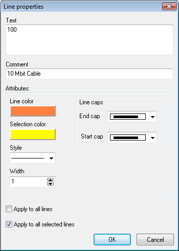
Fig. 1. Line properties window.
![]() Comment is shown when the mouse cursor goes over the line.
Comment is shown when the mouse cursor goes over the line.
![]() When you have finished, exit from the lines adding mode by selecting the same menu item that you selected to enter the mode (or just press Esc).
When you have finished, exit from the lines adding mode by selecting the same menu item that you selected to enter the mode (or just press Esc).
![]() You can delete or change existing lines.
You can delete or change existing lines.
Drawing Areas
![]() You can group several objects on the map by drawing an
area around them and signing it. This will let you create an office (or building) plan having specified department and room numbers.
You can group several objects on the map by drawing an
area around them and signing it. This will let you create an office (or building) plan having specified department and room numbers.
![]() To switch to the area adding mode, select Edit |
Areas | Add & edit mode on the program's main menu. The mouse pointer will change to cross. Then select the new area's
starting point and move the mouse pointer to the area's ending point while holding the left mouse button down. When the mouse button
is released, the window (fig. 2) with the area's properties (border color, selection color, label, comment) will appear on the screen.
After you have entered the required values and clicked OK, the new area will appear on the map.
To switch to the area adding mode, select Edit |
Areas | Add & edit mode on the program's main menu. The mouse pointer will change to cross. Then select the new area's
starting point and move the mouse pointer to the area's ending point while holding the left mouse button down. When the mouse button
is released, the window (fig. 2) with the area's properties (border color, selection color, label, comment) will appear on the screen.
After you have entered the required values and clicked OK, the new area will appear on the map.
![]() While in that mode, you can use the mouse to move or
resize the new area.
While in that mode, you can use the mouse to move or
resize the new area.
![]() To switch to the regular mode, select Edit |
Areas | Add & edit mode on the program's main menu again, or just press Esc.
To switch to the regular mode, select Edit |
Areas | Add & edit mode on the program's main menu again, or just press Esc.
![]() When the mouse pointer appears over the areas, a tip
with data you have entered in the Comment field while creating the area will be displayed.
When the mouse pointer appears over the areas, a tip
with data you have entered in the Comment field while creating the area will be displayed.
![]() If you want to create a text area where the text label is aligned somehow and you want to be able to configure the text font, select the Text area option.
If you want to create a text area where the text label is aligned somehow and you want to be able to configure the text font, select the Text area option.
If you want to place just text without borders on your map, select the Style type with no border.
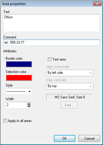
Fig. 2. Area properties window.
![]() If necessary, you can edit existing areas and delete
those that you no longer need. (Edit | Areas | Delete or Edit title and color).
If necessary, you can edit existing areas and delete
those that you no longer need. (Edit | Areas | Delete or Edit title and color).
![]() When the map is exported to file, the areas you have
created will be stored in the file along with other objects data.
When the map is exported to file, the areas you have
created will be stored in the file along with other objects data.
![]() Please read the Hotkeys topic to learn more about effective line and area drawing hints.
Please read the Hotkeys topic to learn more about effective line and area drawing hints.
NOTE:
Learn more about hotkeys and mouse tricks for better network map editing...