The Modbus protocol appeared in the late 70s and is still relevant in the field of M2M (Machine-to-Machine) interaction. It is a network protocol that is widely used in industry for monitoring and integrating various equipment. In fact, Modbus is a de facto standard and is supported by almost all manufacturers of industrial devices and devices. Using the Modbus protocol, you can receive values from sensors and manage controllers. Initially, Modbus used the RS-232 and RS-485 interface in its implementation. Later, a variation of the Modbus TCP protocol appeared, using the Ethernet network for interaction between exchange participants. By default, this protocol uses the TCP port 502.
Modbus devices interact with each other according to the master-slave principle. The master device establishes a connection and executes requests, while the slave can only respond to them. Recently, the Modbus developer has changed the master-slave terminology to the more familiar Client-Server. The client device or software (master) sends requests to the polled server device (slave) and receives responses.
Each Modbus device is identified by a unique address (Slave ID) which can be assigned from the range 1-247. The address 0 is used for broadcast requests from a client to all servers, while addresses 248-255 are considered reserved. In the Modbus TCP, a usual IP address of a device acts as an identifier. However, a standard address may also be required for connection if it is established with an RS485 network through a special router.
A Modbus request consists of a function code and the data to be requested or written to the device. Each function can only operate on a specific data type. There are read-only and write-only functions.
Functions for Reading Modbus TCP Registers
Function Code |
What does the function do |
Value Type |
Access Type |
|---|---|---|---|
01 (0x01) |
Read Coil Status |
Discrete |
Read |
02 (0x02) |
Read Input Status |
Discrete |
Read |
03 (0x03) |
Read Holding Registers |
16 bit |
Read |
04 (0x04) |
Read Input Registers |
16 bit |
Read |
Registers are accessed using a 16-bit address. The first element in each group of registers corresponds to address 0. That is, the address (index) of any register can take values from the range 0-65535. The registers store the values of internal variables, counters, readings of various sensors and flags. Addresses (indices) of the required registers can be found in the documentation for a specific device. They are usually listed in the "Modbus Mapping Table" section.
To read and monitor the parameters of Modbus devices, you can use special programs that support this protocol. 10-Strike Network Monitor Pro allows you to connect to devices via the Modbus TCP and read necessary parameters from them. To read a register, you just need to specify the following parameters:
- Device IP address
- Port (502, by default)
- Slave ID
- Register index
- Function code
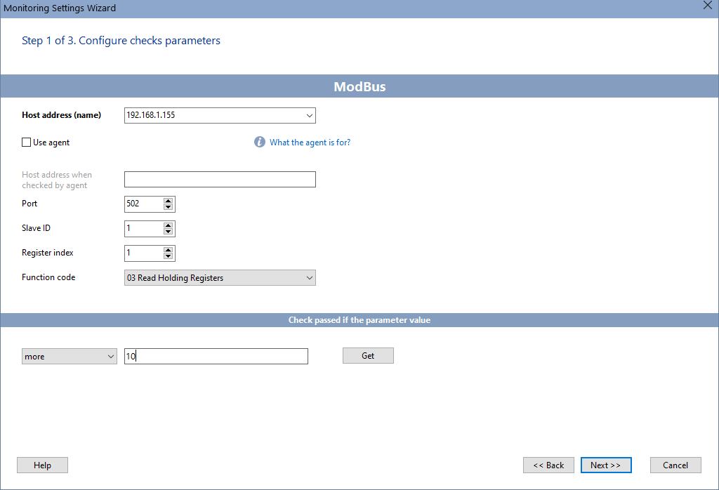
If the monitoring server is not located on the device network, you can connect to it on another network using an Agent (proxy service).
The program can be installed on a server connected to the network #1 and it can connect via Modbus TCP to a device that is connected to another network #2 that is linked to the network #1. For this, you can use a remote agent application, which can be installed on a PC in network #2 with the desired Modbus device. With this scheme, the program will send a request to the agent at the specified IP address, and the agent will forward it to the Modbus device.
When the parameter value goes beyond the specified limits, the program promptly notifies about this in several ways. The alarm threshold can be configured in the check parameters.
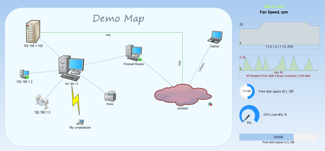
You can display the monitored parameter values on graphic indicators or a SCADA-like scheme, diagram, or map.
Disadvantages of the Modbus Protocol
The protocol was developed over 40 years ago, when the data protection issues were not yet so relevant. It has a number of disadvantages, not only related to security:
- Lack of the authentication and encryption of the transmitted data. To protect them, you need to use VPN tunnels.
- Only the master device can initiate a data transfer. It has to constantly request the slave device, generating unnecessary traffic.
- The slave device cannot track the disconnection from the master.
Despite its age and disadvantages, Modbus is still easy to use. This provides it with a high speed of the industrial implementation. The absence of unnecessary functionality is its main advantage. Modbus is actively developed and supported by many industrial devices from various manufacturers. It is also used by providers when creating cloud IoT platforms.
Warning! This check is only available in the Pro version of the program.
See also:
Requirements: Windows XP/Vista/7/8.1/10/11, Server 2003/2008/2012/2016/2019/2022 supported.